


 1A 3.5V 42x42x20mm 4 Wires (17HS08-1004S)")
 2A 42x48mm 4 Wires compatible with 3D Printer/CNC")


 2.8A 3.2V 57x57x76mm 4 Wires (23HS30-2804S)")
 3A 3.36V 57x57x76mm 4 Wires CNC Stepping Motor")
 4.2A 57x57x114mm 4 Wires CNC Stepper Motor (23HS45-4204S)")


 1.5A 42x42x38mm 4 Wires")
The working principle of linear actuator stepping motor
A linear stepper motor actuator converts stepper motor rotation into linear motion through a screw mechanism. It is used where controlled positioning is required along a straight axis.
How It Operates
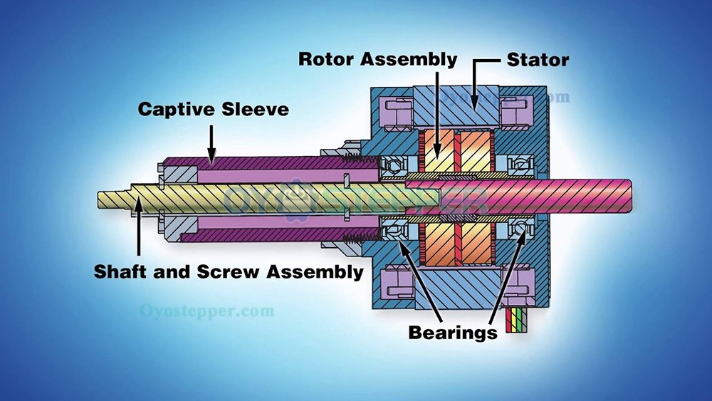
A linear stepper motor actuator consists of a stepper motor coupled to a lead screw or ball screw. When the motor driver applies commanded electrical pulses, the motor rotates in discrete increments. Screw rotation drives a nut along the screw axis, producing forward or reverse linear travel depending on the commanded direction.
The driver receives step and direction signals (or equivalent pulse and direction commands) from a controller and generates the phase currents used to energize the motor windings in sequence. Pulse order determines direction, and pulse rate determines rotational speed, which is converted into linear speed by the screw lead.
Stepper motors move in discrete steps. The linear displacement per command pulse is determined by the motor step angle, the driver microstepping setting (if used), and the screw lead.
Control Requirements
Operation requires a control system that generates pulse commands and a driver that delivers the required winding current. A typical setup includes:
A controller that outputs step and direction commands (or equivalent)
A driver that converts control signals into phased winding current for the motor
Each input pulse advances the commanded motion by one step (or microstep, depending on driver settings). Linear speed is set by the pulse frequency.
Operating Limits
Available torque decreases as speed increases. At higher pulse frequencies, available torque may be insufficient to overcome load inertia, friction, or mechanical resistance. In an open-loop stepper system, loss of synchronization with the command pulse stream can produce position error.
Acceleration and deceleration profiles are commonly used to reduce loss of synchronization. Instead of switching immediately to a high pulse rate, the controller ramps the pulse frequency up during startup and down during stopping to manage inertia and reduce abrupt load changes.
Maximum usable speed and thrust depend on load, supply voltage, driver current limit, motor winding inductance, screw lead, and friction. Performance limits should be evaluated using product-specific specifications and stated test conditions.
Linear Actuators and Rotary Motors
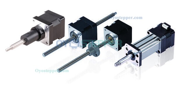
Rotary stepper motors produce angular motion. Linear stepper motor actuators add a mechanical conversion mechanism—typically a lead screw, ball screw, or belt drive—that converts rotation into straight-line movement. The motor operates using the same electromagnetic principles as other stepper motors; the screw or belt mechanism determines the linear output.
Some linear actuators are integrated units with the screw and nut contained within the actuator body. Others use a separate motor coupled to an external screw assembly.
Application Considerations
Linear stepper motor actuators are used in equipment that requires controlled linear positioning. Common integration uses include:
Laboratory and test automation mechanisms
Industrial machinery for pick-and-place and positioning operations
3D printers and CNC machines for axis motion
Optical and instrumentation mechanisms for controlled adjustment
When selecting a linear actuator, evaluate thrust, step resolution (including microstepping configuration), travel length, duty cycle, and speed requirements, along with mechanical guidance, mounting, and alignment constraints.
Previous:Linear Stepper Motor Working Principle
Next:Torque vs Speed Characteristics of Stepper Motor