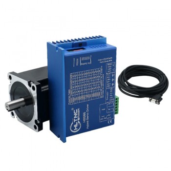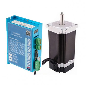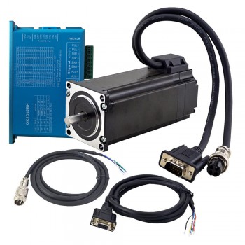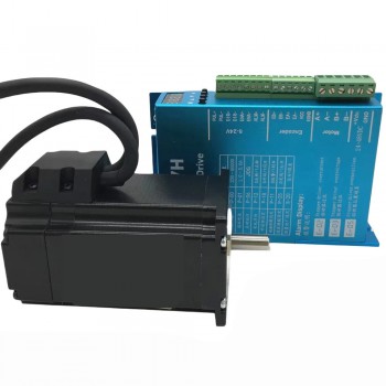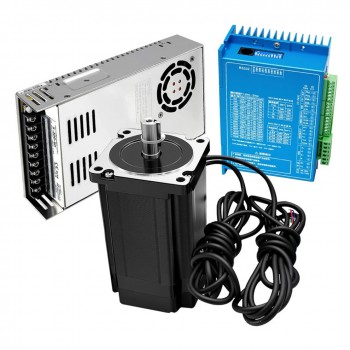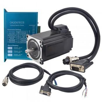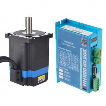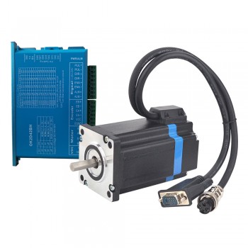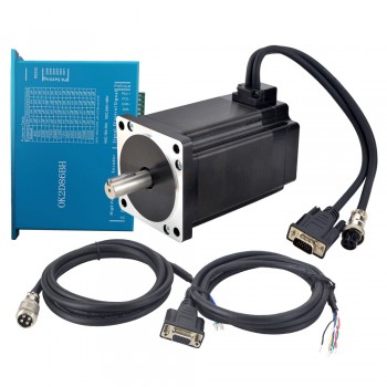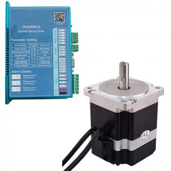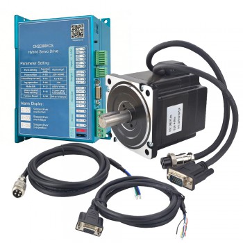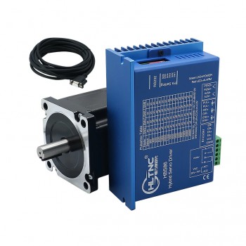





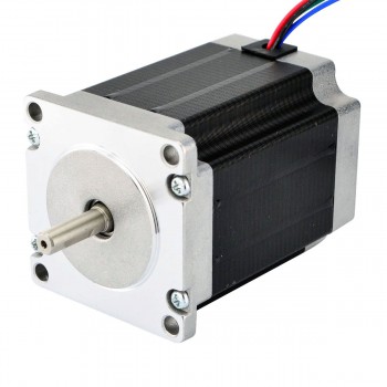
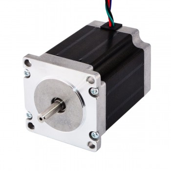
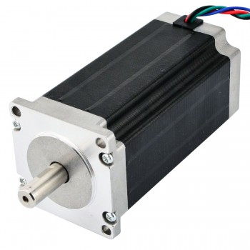
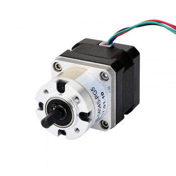

Closed Loop Stepper Motor Kit
How a Closed-Loop Stepper Motor Kit Works
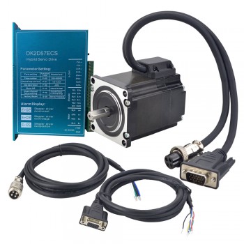
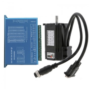
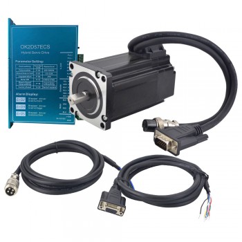
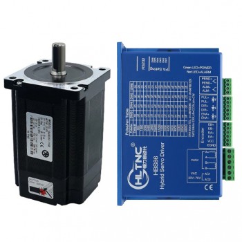
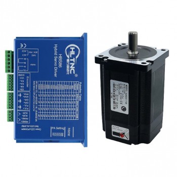
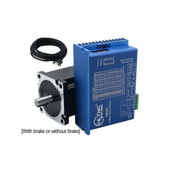
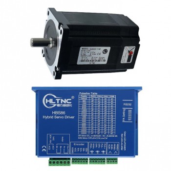
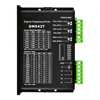
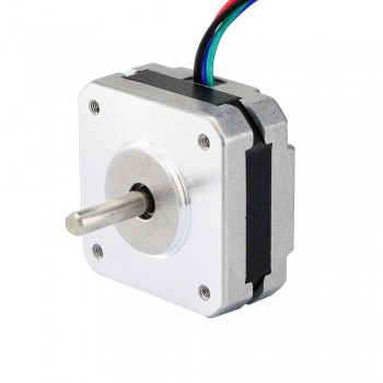
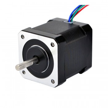
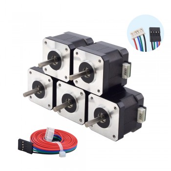
A closed-loop stepper kit pairs a stepper motor with an encoder and a matched driver (with the required cables). The controller sends step and direction commands, while the driver monitors encoder feedback. Based on the drive's control method and limits, the driver can correct for position deviation and report faults through alarm or status outputs when supported.
Selection Notes
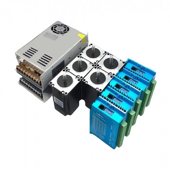
Start with the motion requirement: target speed, load torque, and duty cycle. Then match the motor and drive ratings (supply voltage range, continuous/peak current, and motor electrical specs) and check encoder details such as resolution (CPR) and signal type (single-ended or differential). Confirm your controller interface (pulse/direction or the bus option offered for that series). On the mechanical side, verify frame size, mounting pattern, and shaft dimensions. Kit contents vary by model and may include power supplies, braking resistors, or pre-made cables.
Installation Notes
Route power and encoder cables separately, use shielding/grounding as specified, and allow airflow around the driver. Commissioning usually includes confirming motor phase wiring, verifying encoder direction, and setting current limits, microstep value, acceleration, and following-error thresholds in the setup software. Actual performance depends on sizing and tuning for the intended motion profile.