1A 3.5V 42x42x20mm 4 Wires (17HS08-1004S)")
 2A 42x48mm 4 Wires compatible with 3D Printer/CNC")

 2.8A 3.2V 57x57x76mm 4 Wires (23HS30-2804S)")
 3A 3.36V 57x57x76mm 4 Wires CNC Stepping Motor")
 4.2A 57x57x114mm 4 Wires CNC Stepper Motor (23HS45-4204S)")


 1.5A 42x42x38mm 4 Wires")
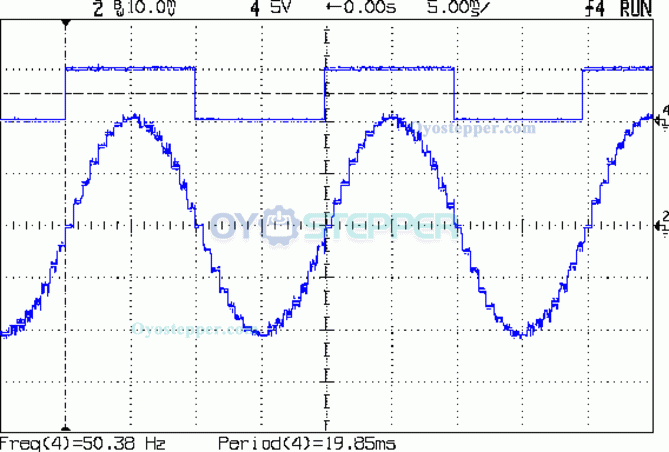
Back emf due to rotation of stepper motor
When a stepper motor rotates it produces a back emf. At the zero lag angle, this is 90 degrees out of phase with the driving voltage, and in phase with the back emf due to inductance. When the motor is producing maximum torque and is on the verge of skipping a step, it is in phase with the current.
Back emf due to rotation is not normally specified on the data sheet, but we can estimate it from this formula:
approximate_peak_back_emf_due_to_rotation = sqrt(2) * pi * rated_holding_torque * revs_per_second / rated_current
The formula assumes that the holding torque is specified with both phases energised at the rated current. If it is specified with only one phase energised, replace the sqrt(2) by 2.
Example: consider a 200 hybrid step motor driving a carriage via a 20 tooth pulley and GT2 belt. That's 40mm movement per rev. To achieve a speed of 200mm/sec we need 5 revs/sec. If we use a motor with 0.55Nm holding torque when both phases are driven at 1.68A, the peak back emf due to rotation is 1.414 * 3.142 * 0.55 * 5/1.68 = 7.3V.
How accurate is this formula? dc42 measured and then calculated the back emf for two types of motor:
17HS19-1684S: measured 24V, calculated 24.24V assuming holding torque is specified with both phases energised at rated current.
JK42HS34-1334A: measured 22V, calculated 15.93V assuming 0.22Nm holding torque with both phases energised at rated current. Perhaps the holding torque for this motor is specified with only one phase energised, in which case the calculated value becomes 22.53V. I have also seen the holding torque for this motor given in a different datasheet as 0.26Nm , which increases the calculated value to 18.05V.
Previous:The working principle of linear actuator stepping motor
Next:How Do Brushless BLDC Motors Work?