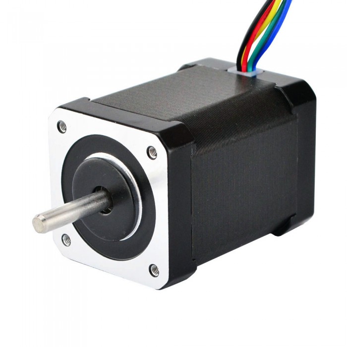
1A 3.5V 42x42x20mm 4 Wires (17HS08-1004S)")
 2A 42x48mm 4 Wires compatible with 3D Printer/CNC")

 2.8A 3.2V 57x57x76mm 4 Wires (23HS30-2804S)")
 3A 3.36V 57x57x76mm 4 Wires CNC Stepping Motor")
 4.2A 57x57x114mm 4 Wires CNC Stepper Motor (23HS45-4204S)")


 1.5A 42x42x38mm 4 Wires")
Quick Start for Beginners to Drive a Stepper Motor
This application note is for novices who want a general quick-start guide showing how to control a stepper motor. Because stepper motors can be used in a variety of ways and are driven by a variety of devices, there is a deal of information available about how these motors work and how to use them. To reduce confusion, the focus of this application note is on stepper motors that can be driven by microcontrollers. This document includes basic information needed to get started quickly, and includes a practical example that is simple and easy to implement. A stepper motor online is an electrically powered motor that creates rotation from electrical current driven into the motor. Physically, stepper motors can be large but are often small enough to be driven by current on the order of milliampere. Current pulses are applied to the motor, and this generates discrete rotation of the motor shaft. This is unlike a DC motor that exhibits continuous rotation. Although it is possible to drive a stepper motor in a manner where it has near continuous rotation, doing so requires more finesse of the input waveform that drives the stepper motor.
It illustrates some basic differences in stepper and DC motor rotation. Generally, a stepper motor consists of a stator, a rotor with a shaft, and coil windings. The stator is a surrounding casing that remains stationary and is part of the motor housing, while the rotor is a central shaft within the motor that actually spins during use. The characteristics of these components and how they are arranged determines whether the stepper motor is a PM or VR stepper motor. The nema 11 stepper motors and nema 17 stepper motors show an example of these internal components. Taking a closer look, the rotor in PM stepper motors is actually a permanent-magnet. In some cases, the permanent magnet is in the shape of a disk surrounding the rotor shaft.
One arrangement is a magnetic disk which consists of north and south magnetic poles interlaced together. The number of poles on the magnetic disk varies from motor to motor. Some simple PM stepper motors such as the one in only have two poles on the disk, while others may have many poles. The stator usually has two or morecoil windings, with each winding around a soft metallic core. Depending upon the polarity of the electromagnetic field generated in the coil (north pole, out of the coil, or south pole, into the coil) and the closest permanent magnetic field on the disk, an attraction or repulsion force will exist. This causes the rotor to spin in a direction that allows an opposite pole on the perimeter of the magnetic disk to align itself with the electromagnetic field generated by the coil. When the nearest opposite pole on the disk aligns itself with the electromagnetic field generated by the coil, the rotor will come to a stop and remain fixed in this alignment as long as the electromagnetic field from the coil is not changed.
Stepper motors have input pins or contacts that allow current from a supply source (in this application note, a microcontroller) into the coil windings of the motor. Pulsed waveforms in the correct pattern can be used to create the electromagnetic fields needed to drive the motor. Depending on the design and characteristics of the stepper motor and the motor performance desired, some waveforms work better than others. Although there are a few options to choose from when selecting a waveform to drive a twophase PM stepper motor, such as full-stepping or micro-stepping, this application note focuses on one called half-stepping.
Previous:Industrial Applications of NEMA 42 Stepper Motor
Next:What is the theory of stepper motors?