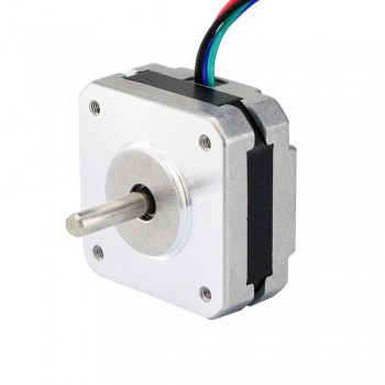
1A 3.5V 42x42x20mm 4 Wires (17HS08-1004S)")
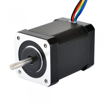
 2A 42x48mm 4 Wires compatible with 3D Printer/CNC")

 2.8A 3.2V 57x57x76mm 4 Wires (23HS30-2804S)")
 3A 3.36V 57x57x76mm 4 Wires CNC Stepping Motor")
 4.2A 57x57x114mm 4 Wires CNC Stepper Motor (23HS45-4204S)")


 1.5A 42x42x38mm 4 Wires")
Astonishing Facts About Two kinds of Stepper Motors
If we wanted to run the stepper motor in unipolar stepper motor mode, that we need to increase the voltage output from the chipKIT uC32 from 3.3V to 5V. We could do this by using some op-amps, but I would personally rather not have to mess with all of the resistors that I would need. A Darlington transistor array, such as TI’s ULN2803, would be less messy. In a nutshell, a Darlington transistor pair has two NPN transistors arranged in such a way so that when a high logic voltage is sent from the microcontroller, the output of the transistor pair will be a low voltage (0V), drawing in current from the 5V center tapped line. However, if a low logic voltage is applied, the output will instead be at a high impedance state, because the NPN transistor will be acting as an “open circuit”. This effectively prevents any current from flowing through the IC, and so no current will flow through the coils of the stepper motor. With no current flow in the coils, no magnetic field is created so the central shaft will not move. You can learn more about how Darlington transistors work here.
For bipolar stepper motor mode, we would need a way either produce a negative voltage or some way to have current flow the other direction through the entire coil, since bipolar mode requires that we do not use the center tapped wire. There is no easy way to get a negative voltage without an external power supply, but we can easily get the current flowing the other direction by using a H-bridge, such as TI’s L293D. H-bridges work by utilizing most transistors, which are able to act like a switch. These transistors are then arranged in such a way that when certain switches are “turned on”, the current will flow through the electromagnet in one direction and when a different set of switches are turned on (and the other switches are left open), the current will flow through the coils in the other direction. You can learn more about how H-bridges work from this Learn module.
If your driver is rated for less current than the motor, that is fine. You just won’t get full performance from the motor. If the driver is rated for more than the motor, you must reduce the current to the motors maximum current. Stepper motor drivers have 4 wire connections for the motors, but steppers motors can have 4, 6 and 8 wire versions. The 6 and 8 wire motors can be used on 4 terminal drivers via special connection methods. These connection methods allow you to choose methods that are more suitable to the electrical and speed requirements of your system. If you don’t know what wires go to what coils, there are a few quick ways to figure it out. The first way is by measuring the resistance between the wires. Pick any two wires. Use a meter to read the resistance between them.
The resistance is generally less than 10 ohms. If you see a resistance near that amount, those two wires belong to the same coil. If the resistance is higher, move one of the probes to a new wire until you do find a low resistance. One of the remarkable features of stepper motors is their ability to position very accurately. This will be covered in depth later on. It has a standard stepper motors have an accuracy of ± 3 arc minutes (0.05°). The remarkable feature of steps motors, though, is that this error does not accumulate from step to step. When a standard stepper motor travels one step it will go 1.8° ± 0.05°. If the same motor travels one million steps, it will travel 1,800,000° ± 0.05°. The error does not accumulate.
Previous:Quick Start for Beginners to Drive a Stepper Motor
Next:What is the theory of stepper motors?