


 1A 3.5V 42x42x20mm 4 Wires (17HS08-1004S)")
 2A 42x48mm 4 Wires compatible with 3D Printer/CNC")


 2.8A 3.2V 57x57x76mm 4 Wires (23HS30-2804S)")
 3A 3.36V 57x57x76mm 4 Wires CNC Stepping Motor")
 4.2A 57x57x114mm 4 Wires CNC Stepper Motor (23HS45-4204S)")


 1.5A 42x42x38mm 4 Wires")
Tips on Wiring a step motor to a driver
Stepper motors are supplied with different lead configurations. Common lead counts include 4-wire, 5-wire, and 6-wire versions. Wiring method depends on the motor lead configuration and the input requirements of the driver.
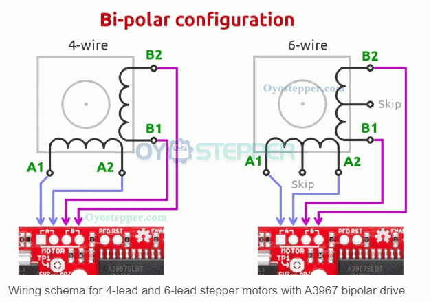
Bipolar wiring
4-wire stepper motor
A 4-wire stepper motor contains two separate coil pairs. For bipolar connection, identify the two wires that belong to each coil.
A common identification method is resistance measurement:
Two wires from the same coil show measurable resistance
Two wires from different coils show no direct continuity
After the two coil pairs are identified, connect one pair to phase A on the driver and the other pair to phase B. Driver terminals may be marked in different ways, such as:
A1, A2, B1, B2
A+, A−, B+, B−
Reversing the two wires within one coil pair changes rotation direction but does not change the coil pairing itself.
6-wire stepper motor used in bipolar wiring
A 6-wire stepper motor has two windings, each with a center tap. For bipolar connection, use the two outer leads of each winding and leave the center tap leads disconnected, unless the motor and driver documentation states another connection method.
A resistance check is commonly used to identify the winding structure:
The resistance measured between the two outer leads of one winding corresponds to the full winding
The resistance measured between one outer lead and the center tap corresponds to part of that winding
After the two outer lead pairs are identified, connect them to the driver phase terminals according to the driver wiring diagram.
Unipolar wiring
5-wire stepper motor
A 5-wire stepper motor is wired for unipolar operation. Its internal winding structure includes a common connection shared by the phase windings. Driver compatibility depends on whether the driver is designed for unipolar input.
6-wire stepper motor used in unipolar wiring
A 6-wire stepper motor can also be connected in a unipolar arrangement when the wiring method matches the driver requirements. In this configuration, the center tap leads are used as part of the unipolar winding connection. The exact terminal arrangement depends on the motor lead identification and the driver terminal definition.
Correct phase order is required for stepping sequence. If phase order is incorrect, the motor may not rotate as intended. Final wiring should be confirmed against the motor technical data and the driver connection diagram.
Wiring identification notes:
Use the motor datasheet when available
Verify coil pairs and center taps by resistance measurement before connecting the motor to the driver
Match motor lead configuration to the driver type before power is applied
Terminal names vary by driver model; use the labeling provided on the driver or in its documentation.
Previous:The difference Bettween 1-phase, 2-phase and 3-phase Motor
Next:Industrial Applications of Brushless DC Motors